Summary
For this lab I took the system of equations established from Lab0x05: Feeling Tipsy? Documentation and developed an open and closed loop model of the ball/platform system. (Please note that my equations from Lab 5 were wrong, so in order to stay up to date, I used Charlie Refvem's matrices posted on piazza here https://piazza.com/class/kjgexlriphb1od?cid=52). I began by linearizing the equations by uncoupling the set of nonlinear second-order equations into an uncoupled set of linear first order equations using Jacobian linearization. Once linearized, I used MATLAB to create an open loop simulation for the system which took inputs for x, theta_y, xdot, thetadot_y, and T_x. Finally, I modified the matrices to create a closed loop simulation that uses K = [-0.05(N-s) -0.02(N-m-s) -0.3(N) -0.2(N-m)] as the controller.
A link to my MATLAB file can be found here: https://bitbucket.org/khchuang/me405-04/src/master/Lab%206/ME405_Lab6.m
Open Loop Simulation Results
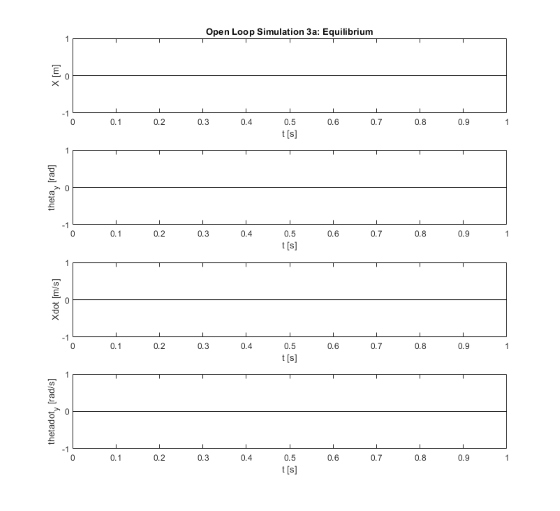
This section details the results from my open loop simulations. I tested four scenarios over the span of 0.4 seconds:
- Equilibrium (All inputs are zero): This plot shows what we expect: no movement in the system.
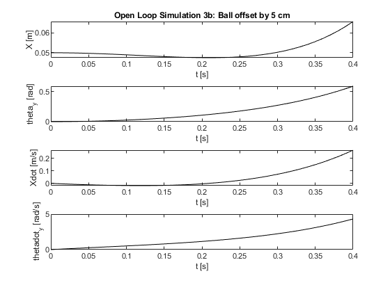
- The ball offset by 5cm: This series of plots demonstrates what we would expect. The ball starts at 5cm but because of the no slip condition, it rotates towards the center of the platform. This is due to the inertia of the ball resisting motion of the plate. Eventually, this is negated and the ball begins to roll away from the center. The platform, on the other hand, rotates towards the side with the ball immediately.
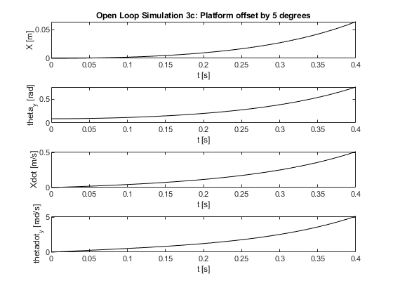
- The platform offset by 5degrees: This series of plots demonstrates what we would expect. Since the ball is centered on the platform, we do not see it roll backwards initally as in the second plot. Instead, all of the parameters strictly increase based on the direction that the platform is offset.
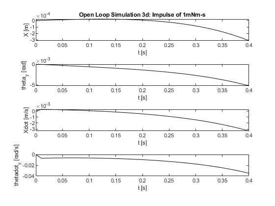
- A 1 mN-m-s impulse applied to the motor: This series of plots demonstrates what we would expect. When there is an impulse applied, there is an initial spike in velocity as reflected in the plots. The platform and the ball position do not react as fast, however, due to their inertial properties.
Closed Loop Simulation Results
This section details the results from my open loop simulations. I tested the same four scenarios over the span of 20 seconds:
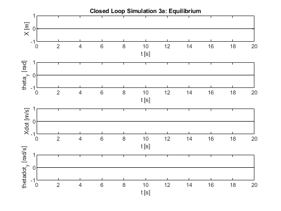
- Equilibrium (All inputs are zero): This plot shows what we expect: no movement in the system.
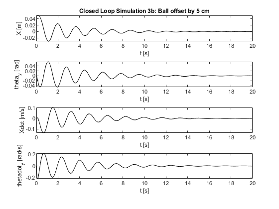
- The ball offset by 5cm: This series of plots demonstrates what we would expect. The ball starts at 5cm but because of the no slip condition, it rotates towards the center of the platform. After that, the controller facilitates the motion to rotate the platform to balance the ball. We can confirm this by comparing the theta_y and X plots. When X deviates from the center, the platform is rotated in the opposite direction to compensate. This process is repeated until the ball comes to equilibrium. Since the controller is made up of arbitraty values, there is significant overshoot and the ball does not stabilize for over 10 seconds.
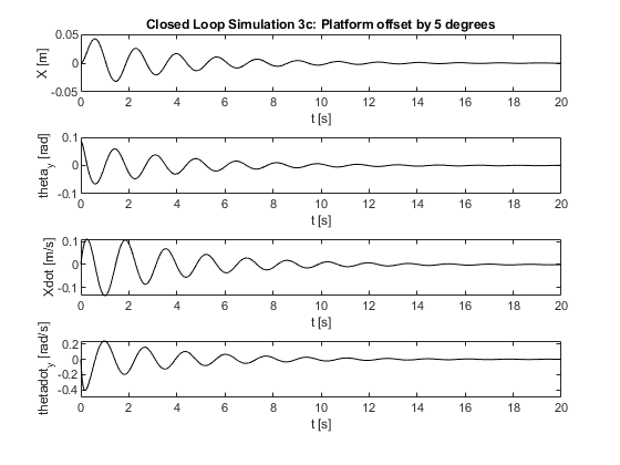
- The platform offset by 5degrees: This series of plots demonstrates what we would expect. It follows the same trend as the open loop model. The platform is initially rotated 5 degrees from vertical and the ball moves accordingly. Then the controller attempts to correct this until the ball stabilizes.
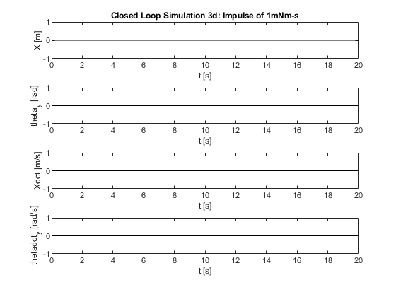
- A 1 mN-m-s impulse applied to the motor: This series of plots demonstrates what we would expect. Since our controller effectively overrides any inputs (motor torques), the impulse would be irrelevant. The result is no motion from the system.
- Author
- Kyle Chuang
- Date
- February 16,2021